A couple months ago
I got into the mood for
low-level programming
and decided I might
learn some assembly language.
I had previously implemented
a Tetris clone
in C
for bare-metal x86,
but it had broken behaviour
and wasn’t feature-complete,
so I decided to give it another try.
I chose the NASM assembler
and targeted i386.
The end result is called Tetrasm,
and is on GitHub.
Booting
Getting a kernel to boot was very simple,
thanks to Multiboot
and having already implemented it
a couple times.
To create a Multiboot kernel,
one simply has to stick some data
at the front of their binary
—
the Multiboot header.
The header consists of
a magic number,
a set of flags,
and a checksum.
In this case,
no flags are needed.
%define MAGIC 0x1BADB002
%define FLAGS 0x0
%define CHECKSUM -(MAGIC + FLAGS)

section .multiboot

dd MAGIC
dd FLAGS
dd CHECKSUM
Simple.
The dd pseudo-instruction
is used to declare double-word data
in NASM.
The header goes in its own section
so that it can be positioned
at the beginning of the binary
in the linker script.
Linking
A linker script can be used
to arrange the various sections
of code (e.g. .text)
and data (e.g. .data)
in the compiled binary.
The Multiboot specification
requires that the header appear
in the first 8192 bytes of the binary.
ENTRY (boot)
SECTIONS
{
  .multiboot 0x00100000 : { *(.multiboot) }

  .text ALIGN(0x1000) : { *(.text) }
  .data ALIGN(0x1000) : { *(.data) }
  .bss  ALIGN(0x1000) : { *(.bss) }
}
This links the Multiboot header
at 0x00100000
(this is where it will be in memory, not in the binary),
followed by each of the conventional sections,
page-aligned.
The first line also declares the entry-point of the kernel,
a label named boot.
Entry
The most important thing
for the entry-point to do
is set up the stack.
For later use,
it’s also a good idea
to initialize the FPU.
%define stack.SIZE 0x1000

section .bss

stack resb stack.SIZE

section .text

global boot
boot:
  mov esp, stack + stack.SIZE
  xor ebp, ebp
  fninit
  jmp main
The stack lives in the .bss section,
or, uninitialized data.
The resb pseudo-instruction is used
to declare uninitialized bytes in NASM.
Since the stack grows down on x86,
the stack pointer esp is initialized
to point to just after the highest address
of the uninitialized memory.
The base pointer ebp is also zeroed,
just to be nice.
The FPU is then initialized with fninit
before jumping to the main label.
It’s also useful at this point
to implement two more functions:
halt and reset.
halt:
  hlt
  jmp halt

reset:
  mov ax, 1
  xor dl, dl
  div dl
  jmp reset
Halt simply executes hlt
in a loop, just in case.
Reset divides by zero,
which triggers a fault,
but since interrupts are disabled
and there are no fault handlers,
a CPU reset occurs.
This is, of course,
not the correct way to reset an x86 CPU.
But it works.
More on that later.
Hello, world?
With Multiboot and stack initialization implemented,
it should be time to get “Hello, world!” on the screen.
Unfortunately,
that actually requires quite a bit more work,
so a no-op will have to do for now.
Build
To build the assembly files,
NASM needs to be run
with the -f elf32 format flag.
The object files are then linked
with ld -m elf_i386 -nostdlib -T linker.ld,
assuming the linker script is linker.ld.
The resulting ELF binary
can then be booted directly by QEMU
with qemu-system-i386 -kernel kernel.elf.
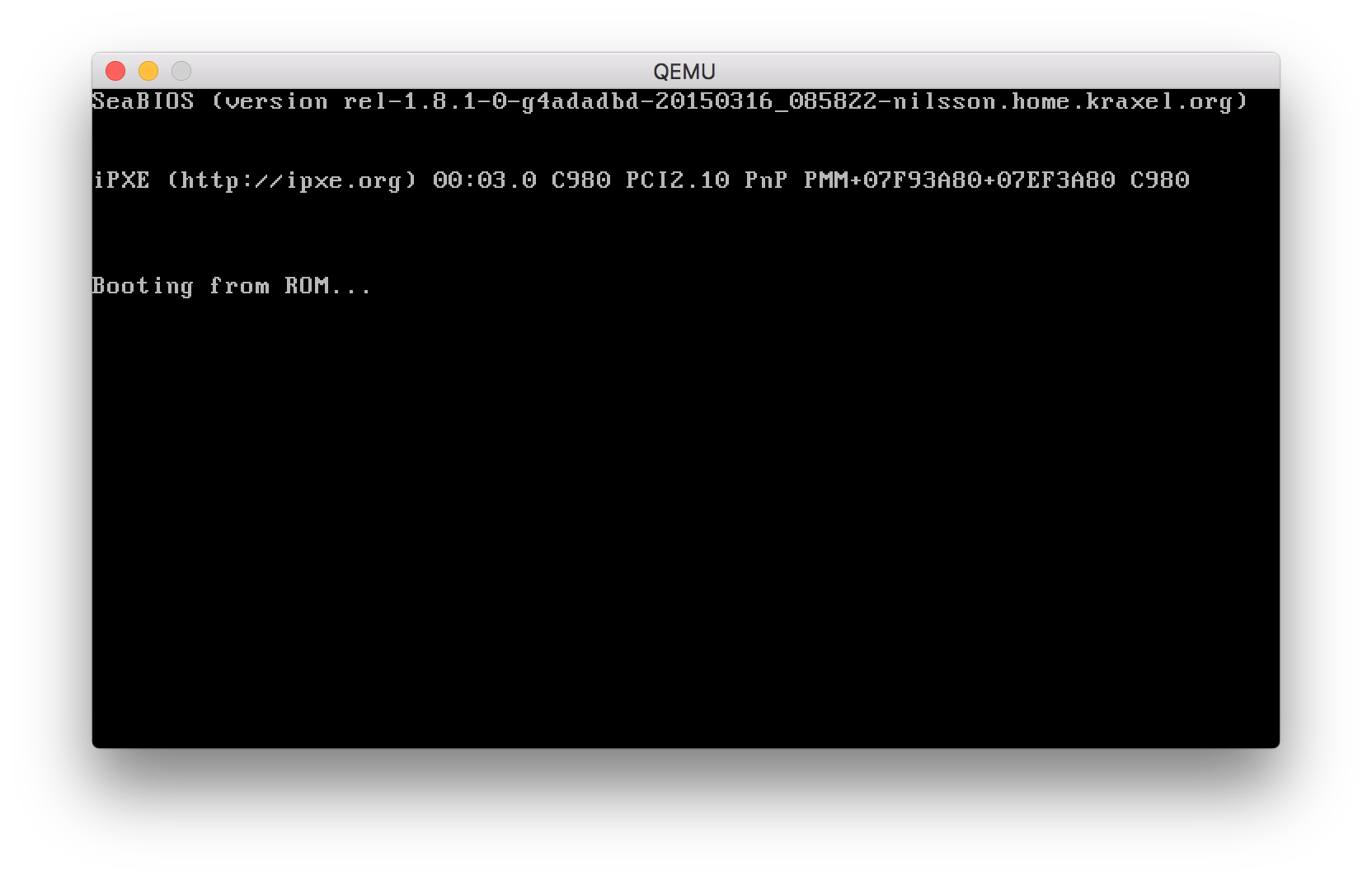
It does nothing successfully.
To see
what this really looked like
early in development,
browse the initial commit
of Tetrasm.
Hello, world!
In order to put “Hello, world!”
on the screen,
some video functions are needed.
Calling convention
The x86 has six general-purpose registers:
eax, ecx, edx, ebx, esi and edi.
The calling convention defines
the first three as “caller-saved,”
and the latter three as “callee-saved.”
This means that
if the calling function
needs the values in eax, ecx or edx preserved,
it is responsible for pushing them onto the stack.
If the function being called
needs to use the ebx, esi or edi registers,
it is responsible for pushing those onto the stack.
Parameters passed to functions
are simply pushed onto the stack
in reverse order.
In order to access these parameters,
the base pointer ebp is pushed
then set to the current stack pointer esp.
This means that parameters can be accessed
starting at ebp + 8
(4 bytes for the pushed original value of ebp
and 4 bytes for the return address pushed by call).
At this point,
esp can also be incremented
to make space for local variables,
which would be at
ebp - 4, for example.
Functions return values in eax.
For example,
a function that takes
three double-word parameters
and uses two double-word local variables,
with all registers being saved,
would look like this.
callee:
  push ebp
  mov ebp, esp
  sub esp, 8
  push ebx
  push esi
  push edi

  ; ...

  pop edi
  pop esi
  pop ebx
  mov esp, ebp
  pop ebp
  ret

caller:
  push eax
  push ecx
  push edx
  push dword 3
  push dword 2
  push dword 1

  call callee

  add esp, 12
  pop edx
  pop ecx
  pop eax
If the initial esp were 0x1000
at the beginning of caller,
the stack would look like this
inside the body of callee.
|
0x0FFC |
Saved eax |
|
0x0FF8 |
Saved ecx |
|
0x0FF4 |
Saved edx |
ebp + 16 |
0x0FF0 |
Parameter 3 |
ebp + 12 |
0x0FEC |
Parameter 2 |
ebp + 8 |
0x0FE8 |
Parameter 1 |
|
0x0FE4 |
Return address |
ebp |
0x0FE0 |
Original ebp |
ebp - 4 |
0x0FDC |
Local variable 1 |
ebp - 8 |
0x0FD8 |
Local variable 2 |
|
0x0FD4 |
Saved ebx |
|
0x0FD0 |
Saved esi |
esp |
0x0FCC |
Saved edi |
Most of the time,
thankfully,
not all registers need to be saved
and local variables are often unneeded.
VGA text mode
In text mode,
each cell or character
on the screen is represented as a 16-bit word.
The upper byte holds the attributes,
i.e. foreground and background color,
and the lower bits hold the ASCII character.
The screen has 80 columns
and 25 rows,
which are mapped to contiguous memory
starting at 0xB8000.
These are useful values
to define as macros.
%define COLS 80
%define ROWS 25
%define VRAM 0xB8000
The attribute byte is further split
into two nibbles (4 bits),
where the high nibble holds the background color
and the low nibble holds the foreground color.
The highest bit of each nibble
can also be set for bright variants of the colors.
There are seven possible colors:
black, blue, green, cyan, red, magenta, yellow and gray.
%define FG.BLACK   0 << 8
%define FG.BLUE    1 << 8
%define FG.GREEN   2 << 8
%define FG.CYAN    3 << 8
%define FG.RED     4 << 8
%define FG.MAGENTA 5 << 8
%define FG.YELLOW  6 << 8
%define FG.GRAY    7 << 8
%define FG.BRIGHT  8 << 8

%define BG.BLACK   0 << 12
%define BG.BLUE    1 << 12
%define BG.GREEN   2 << 12
%define BG.CYAN    3 << 12
%define BG.RED     4 << 12
%define BG.MAGENTA 5 << 12
%define BG.YELLOW  6 << 12
%define BG.GRAY    7 << 12
%define BG.BRIGHT  8 << 12
The values are shifted by 8 and 12 bits
so they can be bitwise-OR into character words.
Clear
The first thing to do is
clear the screen
of the previous output from the BIOS.
The clear function will take
a character/attribute word as a parameter
and write it to every cell of the screen.
It will be using edi for this,
so its prologue and epilogue
will look like this.
clear:
  push ebp
  mov ebp, esp
  push edi

  pop edi
  mov esp, ebp
  pop ebp
  ret
Since it will be writing the same word
over and over,
it can actually duplicate that word
and write half as many double-words.
movzx eax, word [ebp + 8]
mov edx, eax
shl eax, 16
or eax, edx
This zero-extends the word to a double-word,
copies it,
shifts it into the high word,
then ORs the copy back in.
mov edi, VRAM
mov ecx, COLS * ROWS / 2
rep stosd
It then uses the string operation stosd
with rep
to fill the entire screen.
Hello, blank!
Now main can clear the screen.
Getting closer to “Hello, world!”,
I promise.
main:
  push word BG.BLACK | ' '
  call clear
  add esp, 2
  jmp halt
Exciting.
Put string
The function needed to put strings
on the screen, puts, is a bit more complicated.
As parameters, it will take
a pointer to a C-style null-terminated string,
a word of attributes to apply to the whole string,
and a set of coordinates as a word.
It will be using esi and edi,
and needs to be able to exit out of a loop,
so its prologue and epilogue look like this.
puts:
  push ebp
  mov ebp, esp
  push esi
  push edi

  .ret:
    pop edi
    pop esi
    mov esp, ebp
    pop ebp
    ret
Since video RAM is represented as contiguous memory,
the first thing puts needs to do is translate
the coordinate pair into a single offset
in VRAM.
It does so by calculating
offset = y * COLS + x.
In the coordinate word,
the y-coordinate is in the upper byte
and the x-coordinate is in the lower byte.
movzx eax, byte [ebp + 15]
mov edx, COLS
mul edx
movzx edx, byte [ebp + 14]
add eax, edx
Because x86 is little-endian,
the y-coordinate is in the byte after
the x-coordinate.
Next,
edi and esi are set up
to point into VRAM
and to the beginning of the string.
The attributes word is also loaded
into ax.
lea edi, [VRAM + eax * 2]
mov esi, [ebp + 8]
mov ax, [ebp + 12]
The offset in eax is multiplied by two
since the cells are words.
The loop of puts loads characters from the string,
exiting when it hits a null byte,
then writes the character with attributes
into VRAM.
.loop:
  lodsb
  cmp al, 0
  je .ret
  stosw
  jmp .loop
Each character is loaded into al,
leaving the attributes in ah untouched.
For real
Rejoice. It’s finally time.
section .data

hello db 'Hello, world!', 0

section .text

main:
  push BG.BLACK | ' '
  call clear
  push dword 1 << 24 | 1 << 16 | FG.BRIGHT | FG.GREEN
  push hello
  call puts
  add esp, 18
  jmp halt
The coordinates (1, 1)
are pushed in the same double-word
as the attributes.
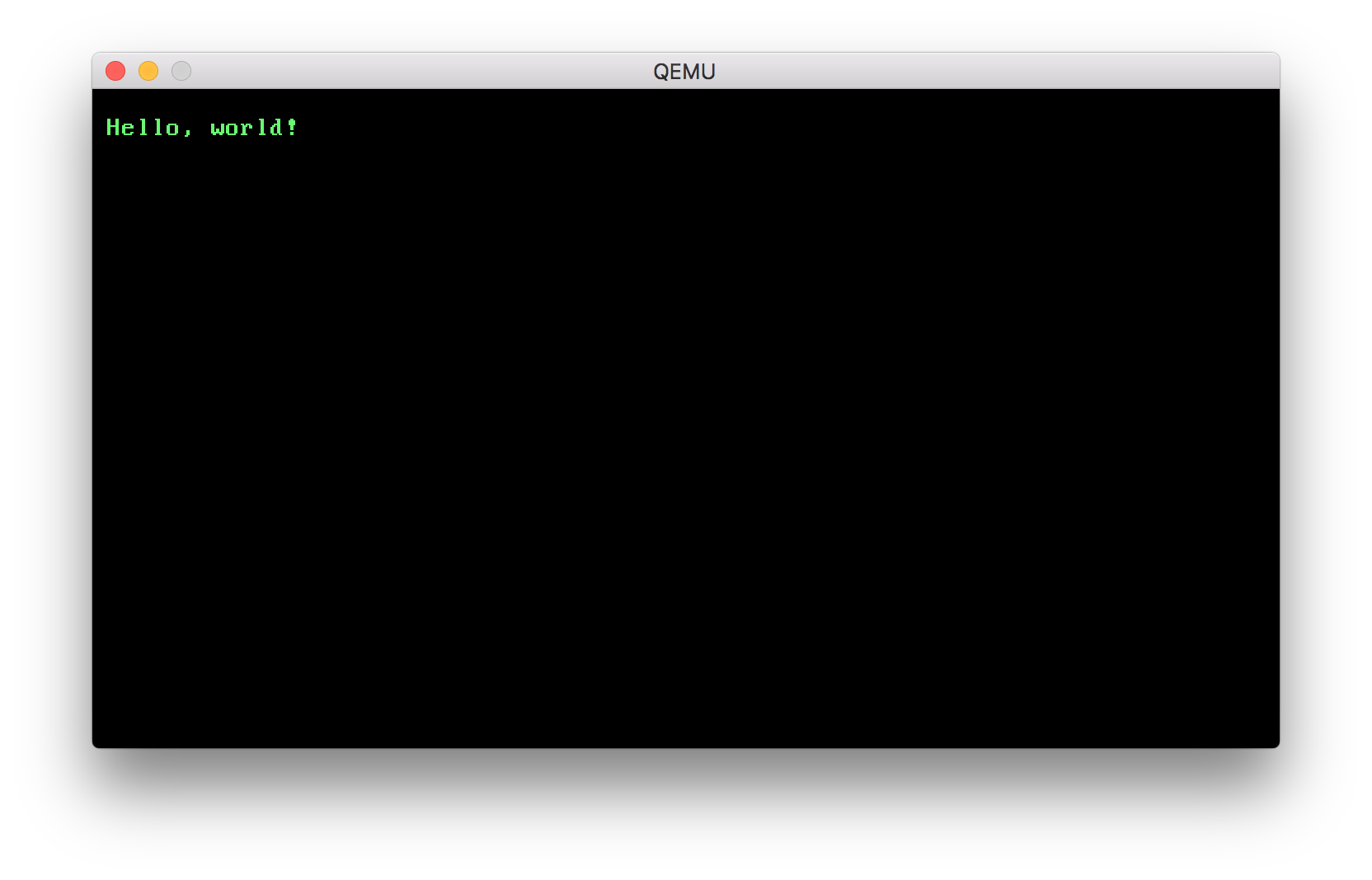
Amazing.
To be continued…
It took a lot longer
than I thought it would
just to get to this point,
and it’s not even close
to Tetris at all.
For now,
it’s a good idea
of what one might do
when starting an OS
in assembly.
Part two and more
will come in the future,
and links will go here.